
Introduction
Inverter heat sinks are essential for maintaining the functionality and lifespan of inverters. Their design requires careful consideration of various scientific principles to ensure efficient heat dissipation and prevent thermal damage. This article explores the science behind inverter heat sink design, examining the factors influencing their performance and the different approaches employed.
Factors Affecting Inverter Heat Sink Design
Heat Generation: The primary factor influencing heat sink design is the amount of heat generated by the inverter. The power rating of the inverter and its efficiency determine the thermal output.
Ambient Temperature: The operating environment temperature also plays a crucial role. Inverter heat sinks must be designed to withstand high ambient temperatures without compromising their cooling capabilities.
Heat Transfer Mechanisms: Heat transfer from the inverter to the heat sink occurs through conduction, convection, and radiation. The heat sink’s surface area, material, and geometry influence these mechanisms.
Types of Inverter Heat Sinks
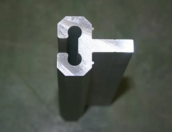
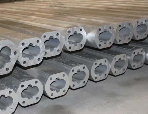
Extruded Heat Sinks: These heat sinks have a uniform cross-section and are formed by extruding aluminum. They are commonly used for low- to medium-power inverters due to their relatively low cost.
Bonded Fin Heat Sinks: Fin heat sinks are composed of a base plate with multiple fins bonded to it. They provide increased surface area for heat dissipation and are suitable for higher-power inverters.
Heat Sink Materials
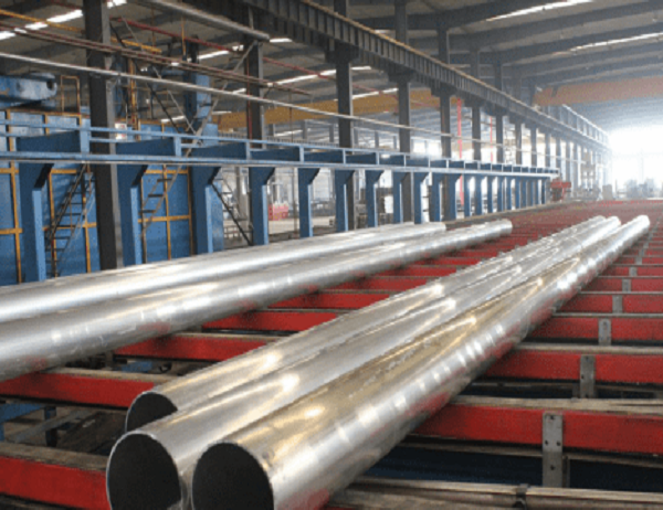
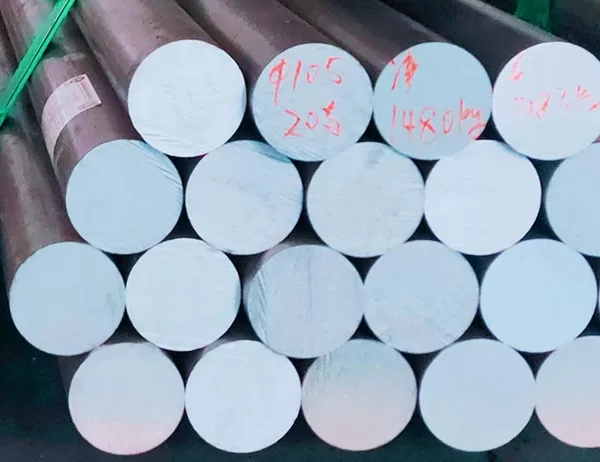
Aluminum: Aluminum is the most commonly used heat sink material due to its high thermal conductivity, low weight, and affordability.
Copper: Copper has a higher thermal conductivity than aluminum but is more expensive and heavier. It is used in applications where maximum heat dissipation is required.
Heat Sink Geometry
Fin Density: The number of fins per unit area determines the surface area available for heat transfer. Higher fin density increases cooling but also increases airflow resistance.
Fin Height: The height of the fins affects the convective heat transfer rate. Taller fins promote better airflow and heat dissipation.
Base Thickness: The thickness of the heat sink base provides structural support and improves heat conduction from the inverter.
Optimization Techniques
Computational Fluid Dynamics (CFD): CFD simulations are used to analyze airflow patterns and optimize heat sink design for maximum efficiency.
Thermal Imaging: Thermal imaging can identify areas of poor heat dissipation, allowing for targeted design modifications.
Prototype Testing: Prototype testing verifies the performance of heat sink designs under real-world operating conditions.
Conclusion
The science behind inverter heat sink design involves a comprehensive understanding of heat generation, heat transfer mechanisms, and material properties. By considering these factors and employing optimization techniques, engineers can design heat sinks that effectively dissipate heat from inverters, ensuring their reliable and efficient operation.