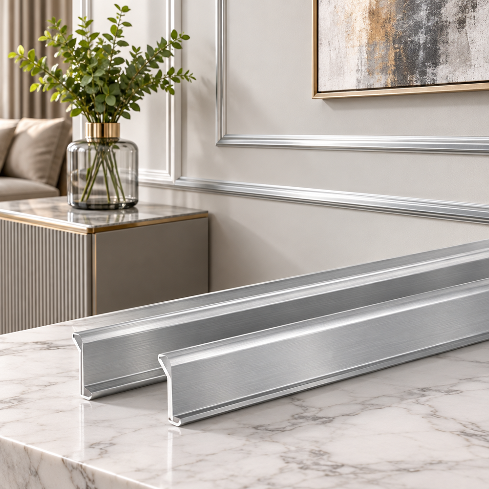
Modern architectural transitions demand crisp sightlines, structural predictability, and long-term durability that conventional materials rarely deliver. Specifying aluminium moulding profiles allows architects, facade engineers, and interior contractors to resolve messy construction junctions into refined visual statements. Whether concealing movement joints between dissimilar substrates or framing high-traffic interior partitions, extruded aluminum components act as the critical transition interface across contemporary building envelopes. When specified correctly, these precision components protect vulnerable wall edges, establish neat shadowlines, and integrate smoothly with diverse finish panels.
Selecting an appropriate cross-section, alloy temper, and surface treatment requires an understanding of material metallurgy, coating performance, and extrusion tolerances. Engineering choices directly affect how these transition pieces perform under everyday thermal movement and building deflection. Below is an engineering guide to evaluating, sourcing, and installing architectural aluminium moulding profiles across commercial, residential, and industrial construction projects, helping project teams achieve durable transitions and clean visual detailing.
Architectural trims were once limited to solid timber mouldings or cold-rolled sheet steel flashings. Modern aluminium moulding profiles, by contrast, are produced by forcing heated aluminum billets through precision-machined steel dies. This extrusion process yields complex, uniform profiles featuring integrated screw bosses, alignment channels, and snap-fit legs that cannot be fabricated via roll-forming. Extrusions provide high repeatability across large building packages, keeping visual gaps uniform from ground floor entries to rooflines.
These extrusions bridge the gap between heavy primary load-bearing structures and lightweight interior finish materials. Designers rely on them to create crisp shadowlines, corner protections, expansion reveals, and perimeter ceiling coves with repeatable dimensional accuracy across expansive wall surfaces. By providing dedicated anchoring and visual transitions, the profiles simplify coordination between wet drywall trades and prefinished cladding systems.
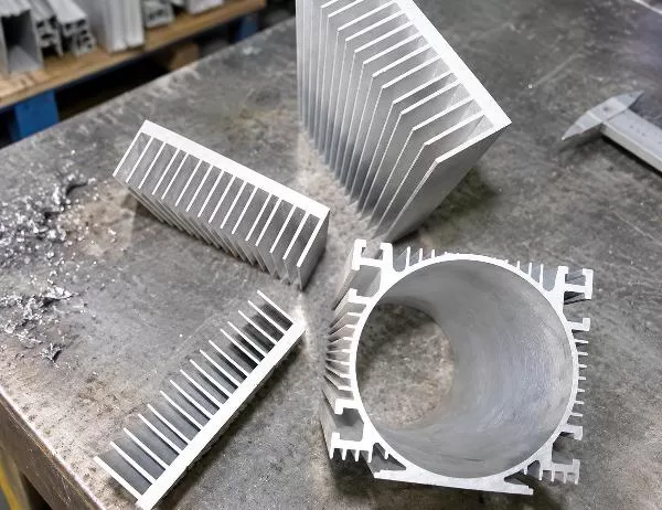
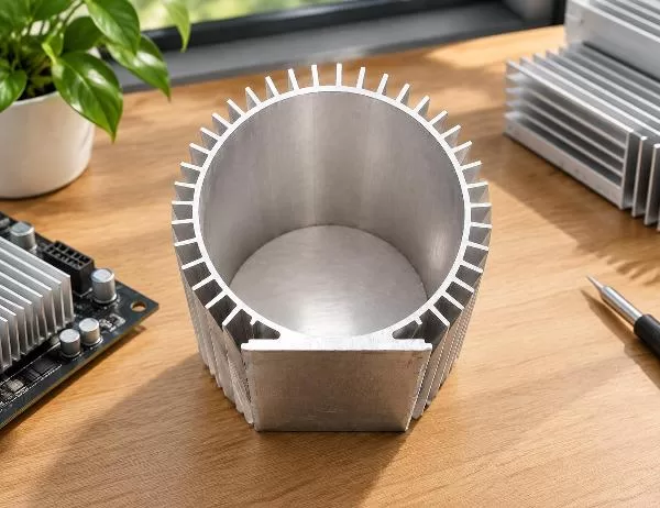
Standard site fabrication often struggles with uneven drywall edges, thermal movement gaps, and misaligned panels. Specialized extrusions address these dimensional variations through purposely designed geometric cross-sections. Profiles often display visible features such as longitudinal underside ribs, downward-extending fins, and serrated channels, though their actual mechanical function—whether intended for adhesive bonding, mechanical alignment, or anchoring—must always be confirmed against the manufacturer’s specific section drawings and installation instructions for the selected model.
The architectural extrusion pictured above demonstrates how functional longitudinal ribs, downward-extending fins, and serrated underside channels are integrated directly into the profile cross-section. Depending on supplier profile drawings and tested assembly details, these underside geometries may facilitate alignment, continuous backing support, or secondary retention. By incorporating these mechanical details into the hidden underside, visible screw heads can be minimized across high-visibility architectural surfaces when following approved installation guidelines.
The 6000-series aluminum alloys represent the backbone of decorative and architectural construction. Among these, alloy 6063 is commonly selected for profiles requiring good extrudability and surface finish, although the final appearance depends on alloy control and processing. With magnesium (0.45–0.90%) and silicon (0.20–0.60%) as primary additions, this material flows predictably through complex extrusion dies, producing consistent profiles that serve as a dependable substrate for subsequent mechanical buffing or chemical pretreatments.
Unlike higher-strength structural alloys such as 2024 or 7075, 6063 exhibits a cleaner surface finish straight off the extrusion press. Its chemical composition limits optical defects during subsequent chemical brightening, polishing, or anodizing procedures, making it widely applied for exposed architectural detailing. Because visual quality remains vital for exposed moulding elements, billet chemical purity and extrusion die maintenance must be verified with the manufacturing plant before placing large commercial orders.
After extrusion, the profile is cooled under a controlled process and then artificially aged to achieve the specified T5 properties. Artificial aging precipitates magnesium silicide phases throughout the matrix, improving rigidity so that trims maintain their intended cross-section during handling, cutting, and site installation. Mechanical values must always be confirmed against the applicable standard, certified mill test reports, and the specific section thickness of the delivered batch.
While 6063-T5 delivers dependable stiffness for secondary framing and visual trims, designers must maintain clear engineering boundaries. Architectural mouldings must not be tasked with primary structural loads without thorough engineering verification. While 6063-T5 can be designed into structural columns and frames under applicable aluminum design standards, decorative trims are generally dimensioned purely for aesthetic transitions, edge protection, and localized panel retention.
Treating 6063-T5 profiles as structural or secondary support members requires project engineers to run dedicated stress and deflection calculations. These calculations must account for the specific cross-sectional moment of inertia, allowable stresses under regional building codes, and connection details, rather than relying on generalized alloy yield numbers. Where primary structural performance or severe impact loads are expected, engineers should determine whether heavy-gauge sections or alternative structural alloys are warranted.
In budget-driven projects, suppliers occasionally thin down profiles to reduce metal weight, but compromising wall thickness creates severe installation failures. For the Goldapple-Alu AE33-6063 product line, nominal thickness is specified at greater than 0.7 mm, providing an optimal balance between profile weight, structural handling stiffness, and die flow efficiency during manufacturing. Maintaining adequate metal cross-sections helps prevent localized distortion during fastener torque application and ensures snap-fit legs retain their intended profile shape.
Wall thickness selection must always reflect the functional demands of the project, including span length, wind loading, and whether mechanical fasteners or adhesive bonds are used. Overly thin walls can twist under heavy thermal stress or deflect noticeably when pressed, meaning that critical retention features and structural anchoring legs should be dimensioned in close coordination with profile structural drawings. Specifying wall thickness alongside allowable deflections ensures trims maintain alignment under building vibration.
Architectural profiles in the AE33-6063 series are available in lengths ranging from 1 to 8 metres based on customer project requirements. Standard 2.4 to 3.0-metre lengths accommodate common floor-to-ceiling heights without horizontal seams. For multi-story atrium wall reveals and long facade curtain walls, custom lengths up to 8 metres eliminate unattractive butt joints, though site access, hoisting limits, and shipping containers must be evaluated in advance.
Accounting for aluminum’s linear thermal expansion coefficient of approximately $23 \times 10^{-6} \text{ K}^{-1}$ is critical when detailing long continuous runs. For example, an 8-metre exterior profile exposed to an effective 40°C seasonal temperature swing will undergo an expansion or contraction of roughly 7.36 mm according to linear expansion formulas:
$$\Delta L = 8000\text{ mm} \times (23 \times 10^{-6}\text{ K}^{-1}) \times 40\text{ K} \approx 7.36\text{ mm}$$
Fastening details must incorporate slotted clearance holes and slip joints to prevent oil-canning, binding, or surface distortion across large facades. Fastener patterns must provide sufficient clearance for this seasonal movement.
Precision architectural joinery requires tight adherence to extrusion tolerance standards, such as EN 755-9 or ASTM B221. Extrusion tolerances are not fixed universal numbers; they vary based on profile dimensions, metal thickness, whether the profile is solid or hollow, and the precision class agreed upon with the extruder. Verifying acceptable limits on die shop drawings avoids costly fitting adjustments when assembling prefabricated trim kits on site.
Anodizing is an electrochemical process where the protective anodic oxide layer is formed directly from the aluminum surface rather than applied as a separate liquid paint film. Because the film is converted from the base metal matrix itself, the resulting finish preserves crisp extrusion contours and fine edge details without the rounding common to thick spray paints. However, actual surface durability and corrosion defense remain dependent on precise anodizing control, seal quality, atmospheric exposure, and ongoing cleaning.
Class I (minimum 18-micron thickness) anodizing is recommended for exterior coastal cladding, while Class II (minimum 10-micron thickness) serves high-traffic interior baseboards and corner guards. Natural clear satin anodizing emphasizes raw metallic industrial aesthetics, whereas electro-coloring with metal salts creates lightfast bronzes, champagnes, and deep architectural blacks. Specifiers should confirm film thickness, seal quality, and color variance ranges before issuing production releases.
Powder spraying provides access to virtually unlimited architectural color palettes via the international RAL system. Thermosetting polyester powders are electrostatically deposited onto pretreated extrusions and cured in thermal ovens, where exact curing conditions depend on the powder formulation and coating supplier’s schedule. Edge coverage must be carefully managed through controlled profile corner radii, proper pretreatment, and regular dry-film thickness inspections to prevent premature edge corrosion.
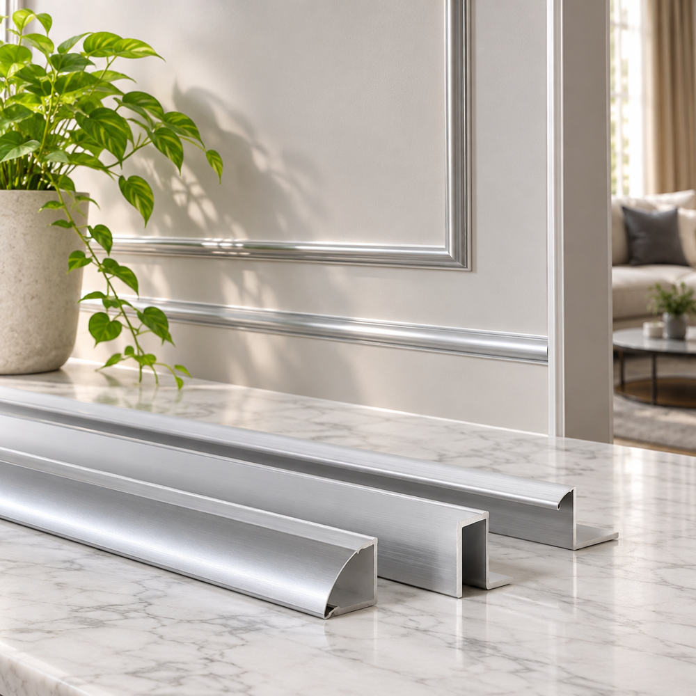
For challenging environments such as high-UV alpine settings or aggressive industrial zones, properly specified architectural PVDF systems can offer strong weatherability. Polyvinylidene fluoride resin systems provide high resistance to ultraviolet degradation and pigment fading over extended outdoor exposures, making them suitable for high-visibility curtain walls and facade trims. Project teams should verify the specific coating schedule, resin concentration, and supplier warranty terms to match project environmental exposures.
Electrophoresis combines an initial anodizing process with a transparent polymer topcoat deposited electrophoretically and subsequently cured in a baking oven. This process may provide a more uniform protected surface than an untreated mill finish, but humidity, chemical, and abrasion resistance must be confirmed for the specified coating system. Proper site care remains essential, as chemical attack from wet construction mortars can still degrade the finish if left uncleaned.
When projects require the warmth of timber without the combustibility, insect vulnerability, or moisture rot of natural wood, vacuum wood grain sublimation transfer offers a practical alternative. Powder-sprayed profiles are wrapped in patterned sublimation films and heated under vacuum pressure, transferring realistic wood grain designs deep into the cured powder layer. This approach delivers the visual character of natural wood alongside the fire performance and stability of metal.
Door and window assemblies rely heavily on extruded moulding sections for glazing beads, sub-sills, drip edges, and interior casing trims. In modern exterior fenestration, these mouldings are engineered to interface with polyamide thermal break assemblies, allowing interior and exterior aluminum profiles to remain mechanically joined while thermal conduction and condensation risks are significantly reduced across the frame. Decorative trim components must never bridge across thermal breaks, preserving overall envelope energy performance.
Internal snap-on cover plates protect fixing screws from moisture infiltration, while dedicated drainage channels direct intercepted wind-driven water safely out through concealed weep slots. The profiles maintain crisp reveals around glass units while housing flexible EPDM sealing gaskets securely. Fabricators must ensure weep paths remain unblocked during profile installation to prevent interior water leaks during severe wind-driven rain events, verifying water management through mock-up testing.
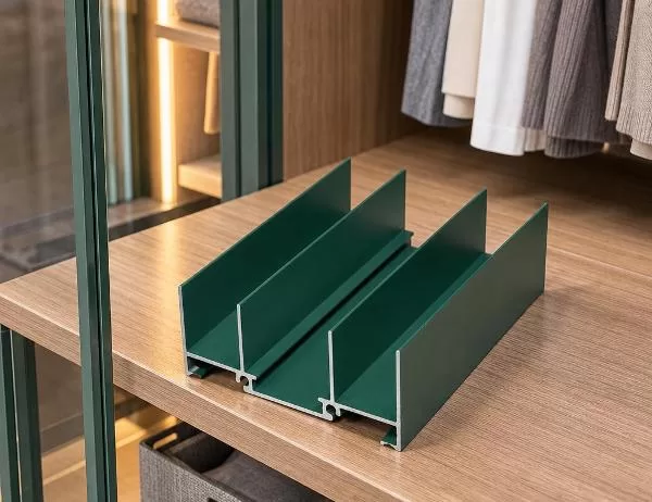
Interior architects utilize extruded profiles to construct suspended ceiling perimeters, wall-to-ceiling shadow gap reveals, and modular partition framework keels. Extruded aluminum perimeter channels maintain straight horizontal lines across vast commercial lobbies where conventional light-gauge steel tracks can bend or twist under site handling. These profiles simplify interface alignment when transitioning between drywall partitions, acoustic panels, and glazed demountable interior walls.
These mouldings integrate directly with gypsum wallboards, fiber acoustic tiles, and decorative backsplashes, maintaining consistent 10 mm or 15 mm recess reveals across thousands of square meters. Their rigid geometry simplifies installation along irregular masonry walls, absorbing minor substrate variations without transferring unsightly deflections to the visible surface. Installers can easily clip trim components into place, significantly accelerating interior framing schedules.
In rainscreen facades and stick curtain wall systems, aluminium moulding profiles perform both decorative and functional roles. They serve as vertical fin attachments, joint pressure plates, snap caps, and horizontal drip flashings across primary envelope assemblies. Incorporating continuous extrusions within exterior facades helps designers establish sharp vertical articulation, maintain water control planes, and hide structural anchoring brackets behind clean architectural sightlines.
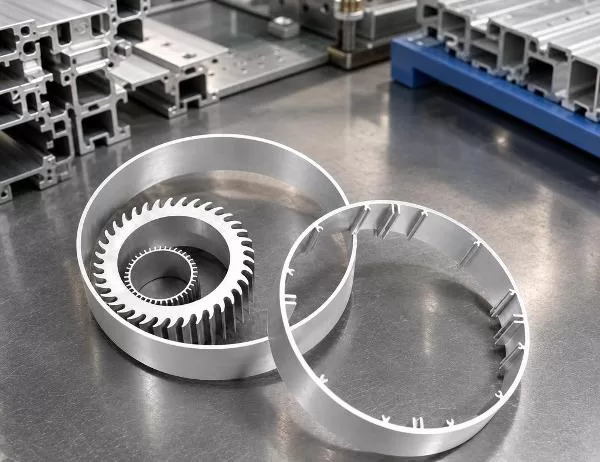
Modern open-plan offices and transport hubs frequently deploy perforated metal acoustic assemblies to control interior ambient sound. Extruded aluminum perimeter frames and stiffener ribs clamp around micro-perforated facing panels to form rigid modular cassettes. The assembly can be configured with acoustic infill, while reverberation and absorption performance must be established through room design and system testing to satisfy building acoustic criteria.
While the extruded profile itself is an acoustically reflective dense metal, its dimensional stability ensures that tensioned acoustic membranes and perforated infill sheets remain flat and vibration-free under mechanical HVAC airflow, preventing annoying rattles. By providing clean peripheral borders and concealed framing, these extrusions allow large acoustic ceilings to look uniform while accommodating overhead service access panels.
Supplying raw extruded lengths is only the first step in successful facade and fit-out execution. Standard site modifications using handheld power tools often compromise finish coatings, create jagged edges, and introduce dimensional errors. High-quality industrial supply depends on coordinated factory deep processing executed in the proper manufacturing sequence, ensuring that prefabricated components fit together seamlessly during job-site erection.
[Step 1: 6063-T5 Billet Extrusion & Aging]
                     │
                     ▼
[Process Path A: Pre-Coating Fabrication] ──> [Welding, Bending, Heavy Machining]
                     │                                      │
                     │                                      ▼
                     ├─────────────────────────> [Surface Finishing: Anodizing / Powder / PVDF]
                     │                                      │
                     ▼                                      ▼
[Process Path B: Post-Coating Fabrication] ─> [Precision Mitering, Hole Punching, CNC Routing]
                     │                                      │
                     └──────────────────────────────────────┴──> [Inspection & Packaging]
Modern profile systems feature factory-punched oval mounting slots to absorb structural settling and thermal movement. Automated multi-axis CNC machines perform mitering cuts down to precise angles, enabling clean 45-degree and 135-degree frame joints without unsightly gaps or misaligned edges. Pre-machined profiles reduce installation time, minimize site cutting noise, and eliminate the risk of burrs damaging weather gaskets.
Integrated drainage slots, mortise cutouts for architectural hardware, and chamfered clearance pockets can be milled directly into profiles. Undertaking these operations in a controlled factory setting drastically cuts job-site labor hours and prevents coating burns caused by abrasive cutting discs. When machining is completed under strict factory tolerances, field assembly errors and material waste drop substantially.
Architectural designs featuring curved walls, barrel-vault ceilings, and arched fenestration require curved aluminium moulding profiles. Stretch-forming and rotary draw bending push 6063 extrusions to specific radius contours, where bending tooling may be selected to limit cross-sectional distortion. The finished curved profile should always be inspected for dimensional changes, wall thinning, and gasket groove fit at the specified radius.
Factory edge chamfering eliminates razor-sharp burrs from saw cuts, protecting installers on-site and ensuring that subsequent powder coatings adhere uniformly over edges without pinhole thinning or edge pullback. Properly beveled profile ends also ease alignment during assembly, preventing tight-fitting corners from chipping or scraping adjoining finishes when components are driven into final position.
Certain high-end architectural transitions require fully sealed, seamless corner joints prior to protective painting. Fabricators utilize tungsten inert gas (TIG) and metal inert gas (MIG) welding processes to fuse miter joints solid into rigid modular frames. Welding bare aluminum sections before coating eliminates unsightly mechanical seam lines, creating continuous perimeter trims for luxury interior foyers and high-exposure entrance portals.
Following welding, mechanical robotic grinding and directional grain polishing blend the joint flush with surrounding profile faces. When this sequence is completed before final surface pretreatment and coating, the finished architectural corner exhibits a monolithic appearance without visible weld beads. Proper weld cleaning and surface degreasing ensure that subsequent anodized or powder-sprayed coatings adhere uniformly across the heat-affected weld zone.
Selecting trimming components requires evaluating physical density, environmental durability, and building code compliance. The comparison matrix below details how 6063-T5 aluminum performs against cold-formed stainless steel, unplasticized PVC, and natural hardwood timber across essential architectural criteria. Comparing these attributes helps architects choose materials that satisfy structural requirements while keeping long-term maintenance within planned facility operating budgets.
| Performance Metric | Extruded Aluminium (6063-T5) | Stainless Steel (Grade 304/316) | Rigid PVC (uPVC) | Architectural Hardwood |
|---|---|---|---|---|
| Material Density | ~2.70 g/cm³ | ~7.93 g/cm³ | ~1.38–1.45 g/cm³ | ~0.65–0.85 g/cm³ |
| Corrosion Performance | Naturally forms protective oxide; vulnerable to crevice chlorides in stagnant moisture | Highly corrosion resistant; susceptible to pitting in marine environments | Impervious to water corrosion; surface degrades if unformulated for UV | Susceptible to fungal rot, swelling, and wood-boring insect attack |
| Thermal Stability | Moderate linear expansion ($23 \times 10^{-6}\text{ K}^{-1}$) | Lower linear expansion ($16 \times 10^{-6}\text{ K}^{-1}$) | High linear expansion ($50–80 \times 10^{-6}\text{ K}^{-1}$) | Anisotropic hygroscopic swelling and shrinkage with humidity |
| Combustibility & Fire | Solid metal core is non-combustible; indicative melting range is approximately 600–650°C depending on composition | Non-combustible base metal; melting point exceeds 1400°C | Combustible polymer; releases hydrogen chloride fumes when burned | Combustible material; fire performance depends on chemical retardants |
| Cross-Section Complexity | Highly versatile (integrated screw channels, ribs, snap legs) | Limited (primarily brake-formed shapes and rolled channels) | Versatile extruded forms, but limited structural stiffness | Milled profiles limited to solid timber geometry |
| Material Recyclability | Aluminum can be recycled repeatedly; actual recovery and energy depend on collection and recycling systems | Readily recyclable through established stainless scrap streams | Difficult recycling down-cycle; separation challenges | Biodegradable if untreated; limited recycling if painted |
While rigid PVC carries lower initial material purchasing costs, its long-term performance outdoors depends heavily on specialized UV stabilizers and impact modifiers. In unformulated or budget vinyl trims, extended solar ultraviolet exposure can lead to yellowing, embrittlement, and noticeable buckling due to high thermal movement. When vinyl trims warp, they can break weather seals and allow water intrusion into vulnerable backing structures.
Architectural hardwood trims demand ongoing maintenance cycles involving sanding, sealing, and repainting to combat moisture intrusion, surface splitting, and fungal decay. Extruded aluminum typically exhibits lower lifetime maintenance demands compared to timber; while routine cleaning remains necessary to prevent dirt buildup, aluminum will never rot, warp, or absorb ambient humidity, making it exceptionally reliable in humid or coastal installations.
Following severe international facade fires, regulatory standards strictly monitor the combustibility of all materials forming the building envelope. Solid aluminum possesses an indicative melting range of approximately 600°C to 650°C depending on alloy composition, although melting temperature alone does not determine structural fire resistance or assembly load-bearing duration during a fire event.
In regulatory fire classifications such as EN 13501-1, bare aluminum may fall within an applicable non-combustible classification route, but the exact product and assembly must be checked under the relevant EN 13501-1 rules. Standard fire test methods like ASTM E136 evaluate bare material combustibility under specific laboratory conditions with defined limitations; multi-component assemblies containing coatings, thermal barriers, and sealants must always be verified under applicable building codes.
Navigating custom profile extrusion sourcing requires clear engineering coordination between design teams and profile manufacturers. The Goldapple-Alu Group manufactures architectural extrusions across a 530,000 m² production base equipped with modern melting, casting, extrusion, and surface treatment lines. For us, maintaining tight process controls across mill finish, anodizing, electrophoresis, polishing, powder spraying, PVDF, wet painting, and thermal break assemblies ensures that technical parameters align with stringent commercial building requirements.
[1. Engineering Definition] ──> [2. Die Assessment] ──> [3. Prototype Extrusion]
                                                                 │
[6. Bulk Production & MOQ]  <── [5. Quality Inspection] <── [4. Sample Approval]
Direct contact between aluminum profiles and dissimilar metals—specifically carbon steel, copper piping, or brass fittings—presents a serious galvanic corrosion risk if an electrolyte like rainwater or condensation bridges the gap. Installers should isolate aluminum surfaces using non-conductive EPDM rubber gaskets, neoprene pads, or specialized isolation barrier tapes. Direct contact with fresh, uncured wet concrete or mortar must also be avoided, as high alkalinity chemically attacks aluminum.
Fasteners securing external trims must be carefully detailed to prevent galvanic degradation and maintain long-term holding capacity. Appropriately selected fasteners, compatible washers, and electrical isolation can reduce galvanic risk; the complete assembly must be verified for the specific project exposure conditions. Correct screw torque also prevents damaging isolation washers or distorting delicate trim profiles during mechanical installation.
Uncured Portland cement mixes, masonry mortars, and highly alkaline wash waters represent serious hazards to finished aluminum extrusions. Fresh concrete slurry frequently exhibits a pH well over 12, which can chemically etch anodized finishes and compromise organic powder coatings, leaving permanent milky white blemishes. Construction schedules should isolate wet plastering and masonry trades from finished trim areas whenever possible.
Aluminium moulding profiles offer significantly higher dimensional stability across changing temperatures, superior mechanical stiffness, and non-combustible base material behavior. While rigid PVC profiles can warp, sag, or embrittle under severe solar heat and ultraviolet radiation unless heavily modified, 6063-T5 aluminum profiles maintain crisp edge alignments over long service periods and accept durable architectural finishes like anodizing and PVDF coatings that withstand diverse exterior conditions.
Alloy 6063 is commonly used for architectural trims because it provides a dependable balance between extrudability and visual surface quality, allowing uniform metal flow into complex dies with minimal surface die lines. Artificial aging to the T5 temper develops dependable mechanical strength, such as a standard minimum yield strength of 130 MPa for profiles up to 10 mm, while providing good handling stiffness and compatibility with decorative anodizing and powder spraying.
While functional minimum wall thickness depends entirely on cross-sectional geometry, span, and service loads, commercial decorative trims such as the Goldapple-Alu AE33-6063 model are specified with wall thicknesses greater than 0.7 mm. Specifying adequate metal thickness helps prevent profile distortion under fastener torque, maintains the mechanical integrity of snap-fit clips, and provides sufficient rigidity for everyday site handling and long-term service.
Because aluminum expands at approximately $23 \times 10^{-6} \text{ K}^{-1}$, expansion joints must be calculated based on the longest continuous profile run, local extreme temperature swings, and the spacing of fixed anchor points. Rather than relying on arbitrary joint gaps, designers should incorporate slotted mounting holes and dedicated expansion sleeves that permit longitudinal sliding without generating oil-canning stresses or buckling across the architectural trim run.
The practical working lifespan of architectural surface finishes depends on the specific coating formulation, local ultraviolet radiation intensity, exposure to airborne salt chlorides, and regular maintenance practices. While high-grade Class I anodized films and architectural PVDF systems offer exceptional weatherability, actual warranty lengths, performance expectations, and maintenance schedules must be confirmed directly against the coating supplier specifications and verified project test reports.
Procurement managers should request copies of current certificates and verify the issuer, scope, and validity for quality management standards (ISO 9001), environmental management (ISO 14001 certification), and metrology systems (ISO 10012). Additionally, buyers should request certified mill test reports documenting alloy chemistry and mechanical test results, alongside separate coating inspection records covering dry-film thickness and adhesion.
Designing architectural spaces requires an uncompromising balance between visual refinement and long-term durability. Integrating engineered aluminium moulding profiles resolves the real-world friction between different building materials, managing thermal shifts, protecting fragile corners, and maintaining clean architectural sightlines across complex assemblies. Whether installed in expansive commercial atriums or exterior facades, extruded aluminum elements provide predictable alignment and structural stability that conventional materials cannot easily replicate.
By prioritizing verified 6063-T5 metallurgy, specifying robust dimensions such as the >0.7 mm wall thickness established on model AE33-6063, matching protective finishes like PVDF or deep anodizing to environmental demands, and partnering with verified manufacturing facilities, construction professionals can detail transitions with confidence. Selecting proven architectural aluminium moulding profiles ensures that high-traffic commercial interiors and demanding exterior facades retain their visual appeal and structural stability through decades of rigorous service.